Bank Network Topology Deployment
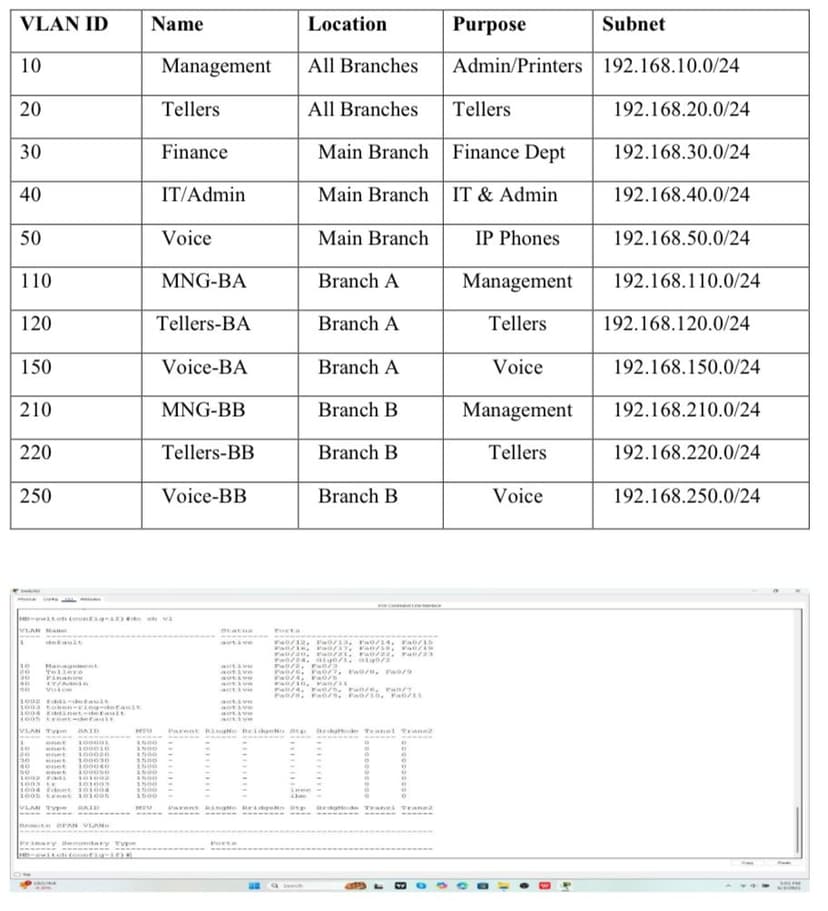
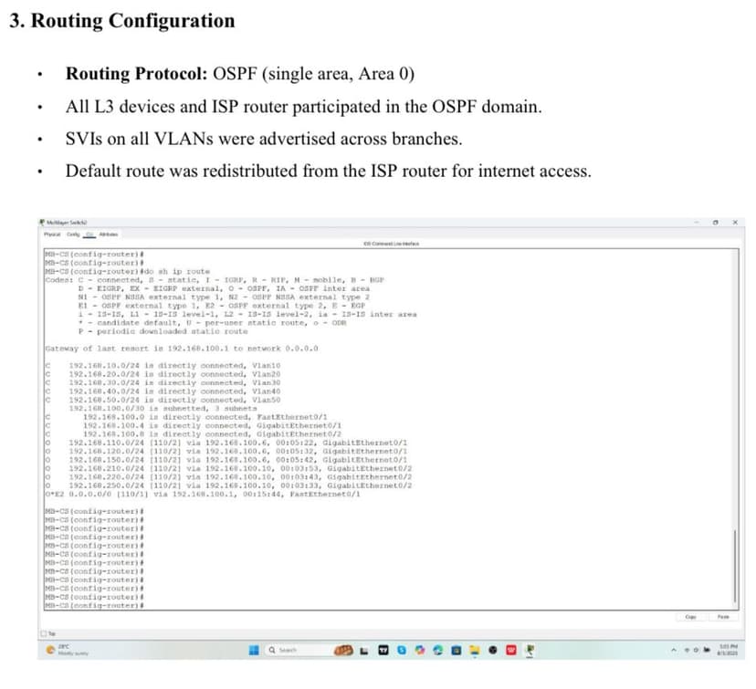
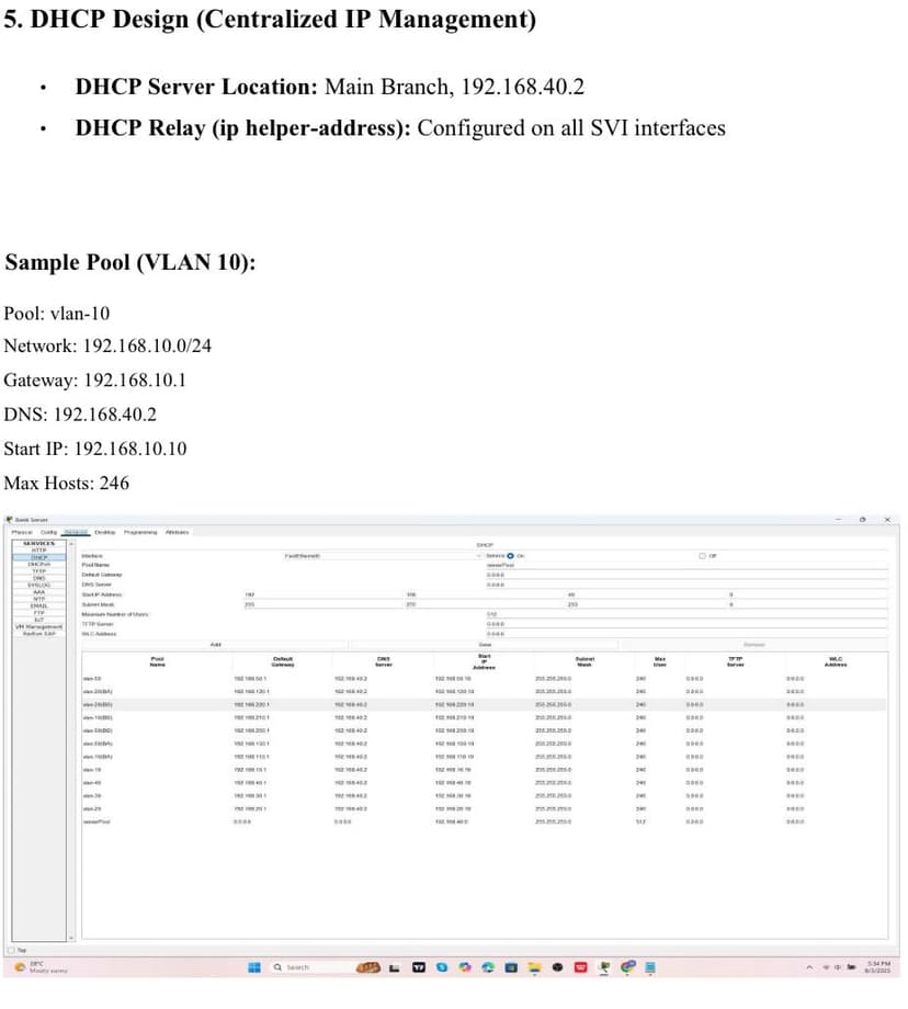
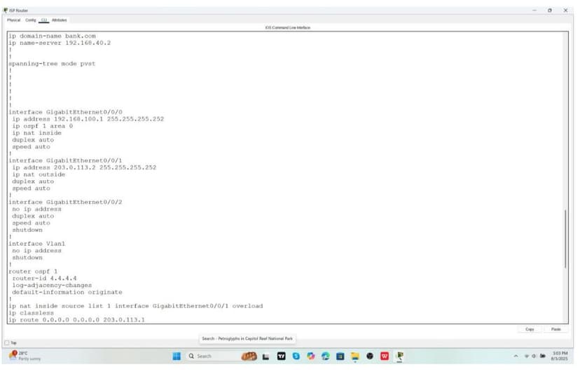
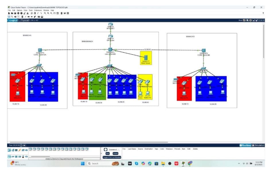
1. Project Overview I designed and simulated a secure, scalable enterprise network for a fictional multi-branch banking institution. The network included: • Main Branch (HQ), Branch A, and Branch B • VLAN segmentation to isolate departments • Centralized IP address management via DHCP relay • OSPF routing for dynamic inter-branch communication • Layer 2 security features to protect against spoofing and unauthorized access 2. VLAN Design & Subnetting Departments were isolated into VLANs with clear subnetting for scalability 3. Routing Configuration • Protocol: OSPF (single area, Area 0) • All routers and L3 switches participated in OSPF • VLAN SVIs advertised across branches • Default route redistributed from the ISP for internet access 4. DHCP & Centralized Management • DHCP server hosted at HQ (192.168.40.2) • DHCP relay (ip helper-address) configured on SVIs • Example: VLAN 10 pool distributed addresses 192.168.10.10–192.168.10.254 5. Layer 2 Security Measures • Port Security: Limited MAC addresses per port with sticky learning • DHCP Snooping: Enabled on user VLANs, trusted uplinks • Dynamic ARP Inspection (DAI): Prevented ARP spoofing • Spanning Tree (PVST+): PortFast enabled on access ports 6. Sample Core Switch Configuration (HQ) hostname MB-CS ip domain-name bank.com ip routing interface Vlan10 ip address 192.168.10.1 255.255.255.0 ip helper-address 192.168.40.2 interface GigabitEthernet0/1 no switchport ip address 192.168.100.5 255.255.255.252 ip ospf 1 area 0 7. Future Improvements • Transition to multi-area OSPF or EIGRP for scalability • Add AAA (TACACS+) for centralized authentication • Integrate Syslog, NetFlow, SNMPv3 for observability • Use ACLs for inter-VLAN restrictions • Simulate ISP redundancy / SD-WAN for resilience 8. Lessons Learned This project trained me to think like both a network architect and an implementer. I practiced balancing clean design with Cisco CLI details, and I left with stronger confidence in building branch topologies that are both secure and scalable.
Team Size
0
Technologies
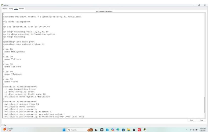
6
Technologies Used
- Achieved full end-to-end connectivity between HQ and branch sites using OSPF, validating inter-branch communication.
- Demonstrated secure VLAN segmentation that prevented unauthorized lateral movement between departments.
- Centralized DHCP provisioning reduced manual configuration and ensured consistent IP management across all branches.
- Layer 2 security (Port Security, DHCP Snooping, DAI) successfully blocked rogue DHCP servers and ARP spoofing attempts in the lab.
- Network design showed clear potential for scalability, with a roadmap to expand into multi-area OSPF, ACL-based segmentation, and redundant ISP links.
- Strengthened ability to balance real-world enterprise requirements (security, scalability, manageability) with Cisco-level implementation in a simulated environment.
Project Gallery